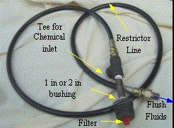
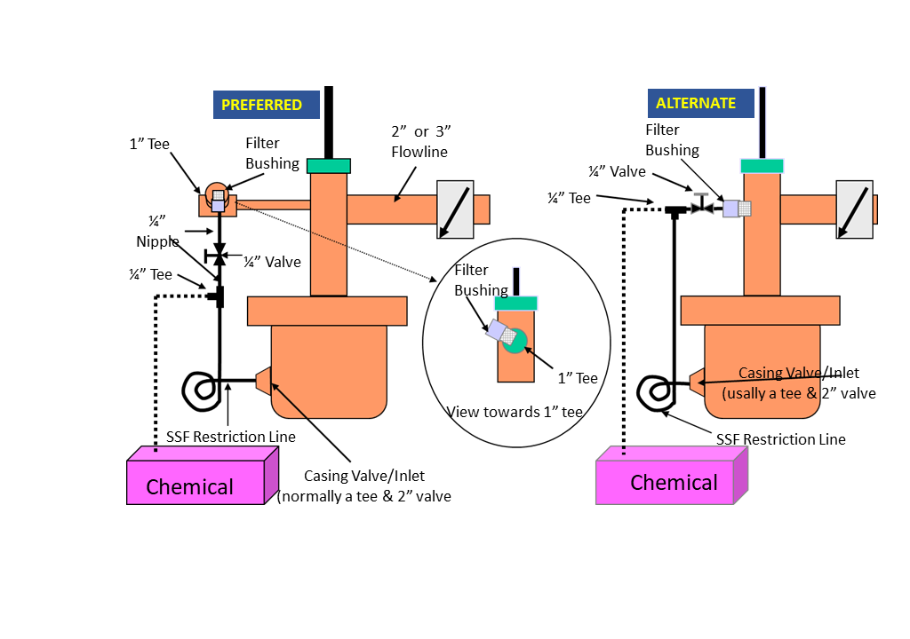
See diagrams below on several options on how to hook up the SFR flowline. Many operators prefer to hook up the Sidestream Flush Restrictor (SFR) on the one inch outlet side of the pump tee. A one inch tee is normally attached to the pump tee with the following installation:
(1) 1 x ¼” bushing (with brass or red plastic filter) screwed into 1” tee.
(2) Bushing is recommended to be above a horizontal inlet position
(3) A short ¼” nipple screwed into bushing
(4) A ¼” ball valve (to allow chemical changes, etc.) screwed into nipple. Not required.
(5) A ¼ x ¼ x ¼ chemical tee screwed into either:
.....a. short nipple (step #3)
.....b. made up into ball valve from step #4 (with another nipple)
(6) The Hydraulic coiled Restriction hose (for pressure drop and restricting rate) mates up to the chemical tee in step #5, no adjustment necessary. Some prefer to screw the 1/4 connection onto the chemical tee with the JIC connection screwed into a 2 x 1/4 bushing connected to the casing inlet. This allows one to disconnect from the casing and flow test the SFR into a bucket (if safe to do so).
(7) Screw JIC connection into a 2 x 1/4 bushing connected to the casing inlet.
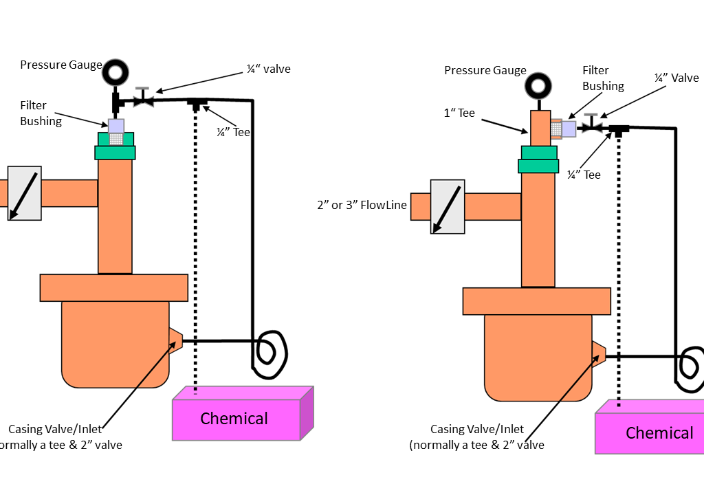
Flowline Side Installation
Installation for Submersible Pumped Wells
† Filter bushing is usually located between horizontal and vertical (on top of flowline tee) and not on bottom of flowline (top half of line or tee).
† Quarter inch valve is normally fully open, used to allow changing SSF line.
† One can let the casing pressure buildup by SI of casing and then open casing with pressure higher than tubing to blow off filter if it gets plugged.
† Ensure all connections and piping are rated for maximum operational pressures anticipated or encountered.
† Many other configurations are possible and operator is responsible for determining the design that best meets their needs.
† Quarter inch valve is normally fully open, used to allow changing of SSF line.
† One can let the casing pressure buildup by SI of casing and then open casing with pressure higher than tubing to blow off filter if it gets plugged.
† Ensure all connections and piping are rated for maximum operational pressures anticipated or encountered.
† Wells producing sand may prefer one inch tee configuration on above right to prevent filter from being sand blasted.
† Many other configurations are possible and operator is responsible for determining the design that best meets their needs.
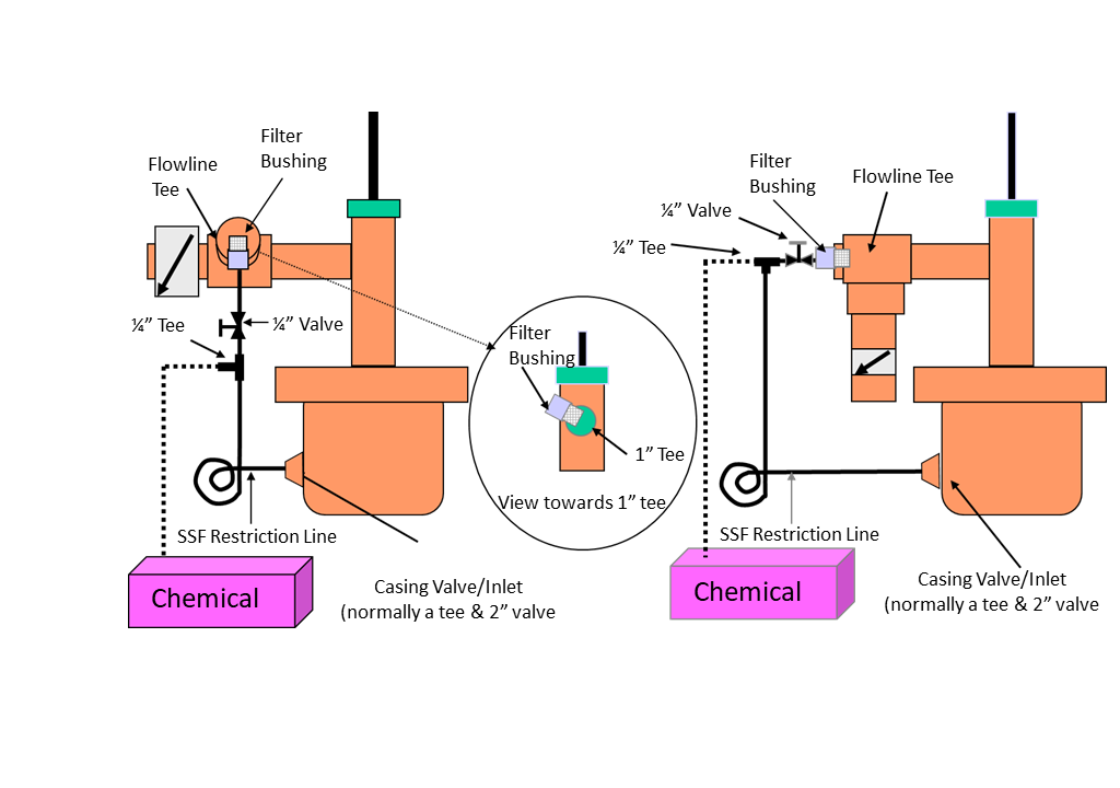
Installation on 1" Pump Tee
† Quarter inch valve is normally fully open, used to allow changing of SSF line.
† One can let the casing pressure buildup by SI of casing and then open casing with pressure higher than tubing to
† Ensure all connections and piping are rated for maximum operational pressures anticipated or encountered.
† Wells producing sand may prefer one inch tee configuration on above right to prevent filter from being sand blasted.
† Many other configurations are possible and operator is responsible for determining the design that best meets their needs.